
INSTRUMENTS FOR TESTING VEHICLES
ISG Fluid Level Sensor
The Fluid Level Sensor detects and reports the presence or absence of fluid by immersion without moving parts.
Products
Salient Features
- The Fluid Level Sensor detects and reports the presence or absence of fluid by immersion without moving parts.
- For use in a wide variety of non-explosive fluids and range of operating temperatures.
- Typical applications include:
- Water – 50/50 antifreeze coolant
- Automatic Transmission and Hydraulic Fluid
- Engine Oil
- Typical operating temperatures range from -30C to +120C.
Working Principle
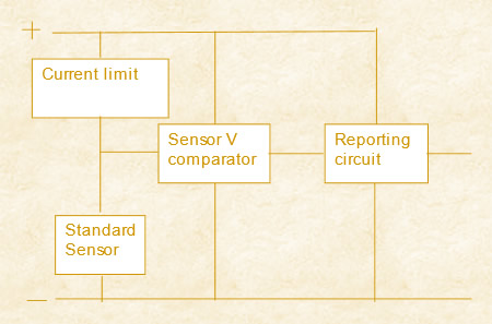
- Uses the non-linear properties of doped silicon to detect a liquid or excessive heat in conjunction with a current limiter and heat sink.
- As the temperature of the sensor changes, so does the voltage across it - thermally variable resistor.
- The change is modest within the operating window, but extreme once removed from fluid.
- Uses "self heating property"
- Select trigger V between in fluid and air.
Basic Sensor Type (Standard or FLSW)
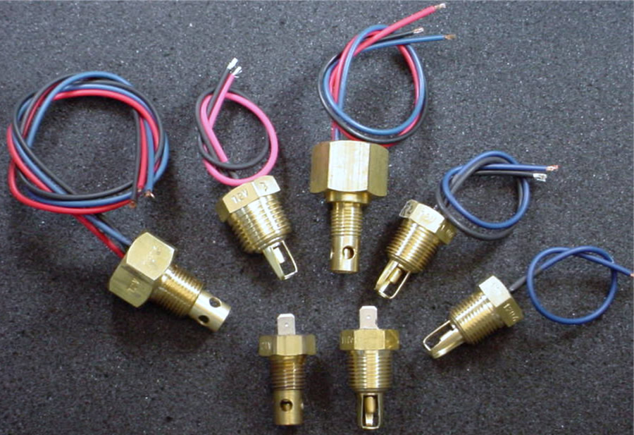
The sensor comes in 2 varieties: Standard and Switch; each is available in 2 nominal voltages: 12 Vdc & 24 Vdc. Sensors are fitted with 6.5", 18 Ga., GXL type wires as standard connections. Other termination schemes are supported.
The Standard sensor contains only the sensing element in a standard National Pipe Threaded brass housing and requires only 2 electrical connections - Power and Ground. The sensor state is determined by monitoring the Power lead voltage with external circuitry.
The Switch model sensor incorporates a switch (Normally Open or Normally Closed) driven by the sensor element enclosed within the brass housing to drive a sensor status signal - Ground is common and only power needs to be supplied.
Categories of Sensor
- By type of Construction
- By type of Die
FLSW
This is a three wire system where there are 2 power in wires (+,-) and a third status wire that reports whether the sensor is either in or out of fluid on an internal PCBA. There are 2 variations of the status reporting: one is a normally open circuit to ground that closes and conducts when out of fluid, and the other is the reverse, that conducts when in fluid then opens when out of fluid. Functionally it is the same as the standard sensor except that the added PCBA replaces the customer’s drive and monitoring circuit. The added PCBA raises both the minimum turn on voltage and maximum withstanding voltage due to the voltage drop of the PCBA. The 12v PCBA uses a 12 Ohm sense resistor while the 24v PCBA uses an 80 Ohm sense resistor.
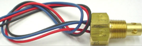
FLSW 3 Wire
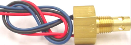
FLSW 4 Wire
Available in 3 Different Configurations
Each general sensor type can be specified with any one of the 3 dies (sensing active element). The die is chosen upon the desired voltage operating range and type of fluid being sensed. The die changes in resistance with internal heating, such that a hot die has a low resistance. To report that the sensor is in fluid, the internal heat of the die is kept high by losing heat to the fluid surrounding it. When the die is surrounded by air, its heat builds up thus decreasing the die’s resistance.
The dies are:
K12
This is the physically smallest of the 3 dies. It was chosen by the original designer for use in antifreeze/coolant fluids in a 12v nominal system. It does not perform well in more viscous fluids such as oils. Some sensor PNs require K12 dies hand selected for turn on by 9.6v. Others require turn on by 10.8v but their maximum withstanding voltage also is proportionally higher.
LS12
This is the physically largest die. It was chosen by the original designer as a general purpose sensing element as it work with both coolant and oils in 12v nominal systems, but at a slightly higher turn on voltage and thus also a higher maximum withstanding voltage. This is the only one of the 3 dies that we have been successful in re-creating. Turn on voltage requirements range from 10.8v up to 15.6v.
LS24
This is the middle sized one. It is specifically used for all 24v nominal systems in all fluids. Turn on voltage is around 18v and maximum withstanding voltage can be in excess of 28v using hand selected parts.
By Type of Whisker
This makes the electro-mechanical connection between the die and the outside world. There are 2 of them:
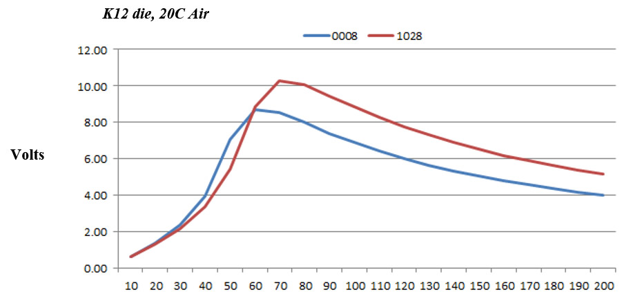
- M46-0008-00 : This is the original whisker. It has a cross-sectional area of 0.064 uin2. The smaller cross-sectional area doesn’t leak as much heat away from the die, so it does not perform as well in hot oils.
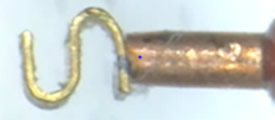
- M50-1028-00 : This whisker was added in 2010 and has a cross-sectional area of 0.080 uin2. The larger cross-sectional area leaks more heat away from the die allowing it to run cooler in hot oil applications, raising the turn on voltage and thus achieve a higher withstanding voltage.
mA
By Type of Fluid (Viscosity, thermal carrying capacity)
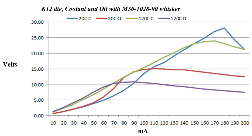
The ability of a fluid to wick away heat is what makes these sensors work. The more viscous the fluid, the less able it is to keep the die cool so that its resistance doesn’t drop. Thus, a given sensor will not be able to withstand as high a voltage in oil as it does in coolant. This is compounded if the fluid is also hot, as it won’t take as much extra heating to overwhelm the sensor’s ability to withstand a higher voltage, so the hotter the fluid, the lower the withstanding voltage.
Temperature of the Fluid Being Sensed
The ability of a fluid to wick away heat is what makes these sensors work. For a given fluid, as the temperature of the fluid increases, it also raises the internal temperature of the die, so that the sensor will not be able to withstand as high a voltage as it did when cool. If the fluid is hot, it won’t take as much extra heating to overwhelm the sensor’s ability to withstand a higher voltage, so the hotter the fluid, the lower the withstanding voltage.
Minimum voltage in order for a sensor to function
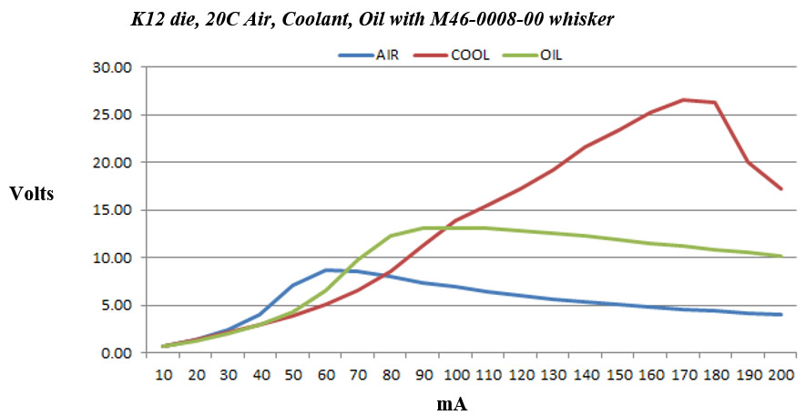
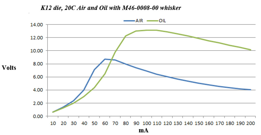
In order for a die to be heated sufficiently to drop its internal resistance enough, there must be an adequate amount of current flowed through it (Ohm’s Law: P=I2*R). In order to develop that current, there must be enough voltage across the die to reach that peak point. This is the turn on voltage. The amount of heatsinking the die experiences can move that point: thicker whisker, less viscous fluid, cooler fluid, and some manufacturing issues with the solder joint to the cup. Refer to graph below: minimum turn on voltage is that maximum voltage peak of the AIR curve. Once the die crests the peak, then the sensor will reduce its resistance as it heats up, dropping the voltage across it. Note that changing the whisker or addition of a PCBA will affect this value.
Maximum voltage a sensor will withstand before false trigger
Since the die responds to internal heat and the internal heat and is a function of both the external heat as well as the current flowing through the die, then it is possible to drive a sensor into a false failure mode by either exceeding the environmental temperature or overdriving the sensor input voltage even when the sensor is bathed in fluid. This is the maximum withstanding voltage. As the environmental temperature increases, so does the internal heat of the die, thus it will take less current flowing through the die to raise its internal temperature to the point at which it starts to drop its resistance and the sensor now reports it is out of fluid, even if it is still in fluid. This point can be modified by changing the fluid type (viscosity), fluid temperature or whisker. Refer to graph below: maximum withstanding voltage is that maximum voltage peak of the fluid (COOL or OIL) curve. Once the die crests the peak, then the sensor will reduce its resistance as it heats up, dropping the voltage across it. Note that changing the whisker or addition of a PCBA will affect this value.
In Summary
In summary, the variables listed interact with each other so the performance of a given sensor is a balancing act between all the variables and manufacturing variation. If the goal is to tighten the specification, then elimination of variables is the most efficient way to accomplish that.